New product 16×32 RGB LED panel + Arduino Uno connector shield Embedded Lab
Arduino rgb led adviserfiln
The Adafruit_RGBLCDShield library is a derivative of the LiquidCrystal library that comes with Arduino so you can call any of the functions that you're used to and they'll work just the same. There are two extra functions you may want to use. One is lcd.setBacklight (color); which will change the backlight color assuming you have an RGB LCD on.

RGB LED with Arduino 101 Oscar Liang
This sketch was written for either of the 2.1" Round 480x480 RGB-666 displays. Now upload the sketch to your Qualia ESP32-S3 and make sure a round display is connected. You may need to press the Reset button to reset the microcontroller. You should now see a circular rainbow appear on the display! Here are some pre-compiled UF2s for various.
.jpg)
Gravity I2C 16x2 Arduino LCD with RGB Backlight Display Smart Engineering Solutions
Step 2: Connect the GND pin on the color sensor module with Arduino. Step 3: Connect the I2C data line next. Step 4: Connect the I2C Clock line. Step 5: Connect the power pin. TCS34725 Library Installation And Arduino Code Examples. Step 1: Open Library manager. Step 2: Search for the Adafruit Library.

Using the ST7735 1.8" Color TFT Display with Arduino ElectronicsLab Arduino, Arduino led
Chris's Arduino sketch lets the user "print" alphanumeric characters to scroll across the four LED matrices. The best part about this design (other than the great style) is that Chris can scale it up in the future with larger host boards that accept more than four LED boards. You can follow any responses to this entry through the RSS 2.0.

RGB LED Arduino Shield Renewable Energy Innovation
Arduino_GFX is a GFX library for various color displays with various data bus interfaces Arduino_GFX is a Arduino graphics library.

michaelsarduino TFT Display mit Arduino verwenden
Otherwise, the panels will not be able to display as expected due to the limitations of the library and the Arduino Uno. To daisy chain two 32x32 RGB matrices together, connect another IDC cable from the output of the first panel to the input of the second panel. Then connect the second 4-pin polarized connector to the input power connector.
Arduino Project 27Arduino RGB LED experiment
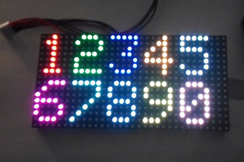
One has 512 bright RGB LEDs arranged in a 16x32 grid on the front, the other has 1024 LEDs in a 32x32 grid. On the back is a PCB with IDC connectors (one set for input, one for output: in theory you can chain these together) and 12 16-bit latches that allow you to drive the display with a 1:8 (16x32) or 1:16 (32x32) scan rate. COMPATIBLE HARDWARE
GitHub a3alamgi/RGB_Display A 16x16 RGB display controlled with Arduino Mega using TLC5940
Looking for Rgb Display Arduino? We have almost everything on eBay. No matter what you love, you'll find it here. Search Rgb Display Arduino and more.

PANTALLA DISPLAY TFT ARDUINO ST7789 1.3P 240X240 RGB IPS LCD SPI 65K IC ⋆ Starware
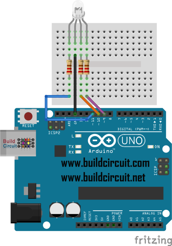
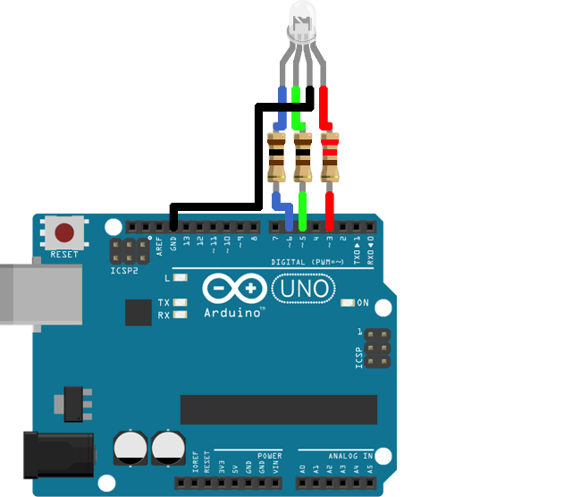
There are two types of RGB LEDs: Common Anode and Common Cathod e. We'll provide example schematics and code for both types below. How To Connect an RGB LED to an Arduino Here's the schematic for the circuit. This diagram uses three resistors and a common anode RGB LED (you'll find the schematics for a common cathode below).

Arduino RGB LED Module 4 Steps (with Pictures) Instructables
Guide for WS2812B Addressable RGB LED Strip with Arduino This post is about the WS2812B LED strip, which is an addressable RGB LED strip. The information in this post also works with other similar LED strips, such as strips of the WS28XX family, Neopixel strip and others. Introducing the WS2812B LED Strip

Adafruit RGB Matrix Shield for Arduino Arduino, Arduino projects, Arduino projects diy
Step 1 - Connecting the RGB LED. RGB LED Basics. Common Cathode and Common Anode RGB LEDs. Controlling the LED Brightness with PWM. Step 2 - Connecting the Three Potentiometers. Using a Potentiometer as an Analog Input. Step 3: Arduino RGB LCD Example Code. How the Code Works. Additive Color.

16x16 RGB LED Panel Arduino Projects 5 Steps (with Pictures) Instructables
Before we get into the Arduino RGB LED configuration, wiring, etc. Let's first go over the basics of the RGB LED itself. The RGB LED consists of 3 LEDs in one. A red, a green, and a blue LED all in the same housing with separate leads for each. This allows the LED to mix colors at different intensities, allowing the presentation of many.
New product 16×32 RGB LED panel + Arduino Uno connector shield Embedded Lab
In order to get red light on the LED we will call the setColor () function and set value of 255 for the redValue argument and 0 for the two others. Respectively we can get the two other basic colors, green and blue. For getting other colors we need to mix the arguments values. So for example if set all 3 LEDS to maximum brightness we will get.

Arduino Powered Three Color 8x8 Led Array Instructables
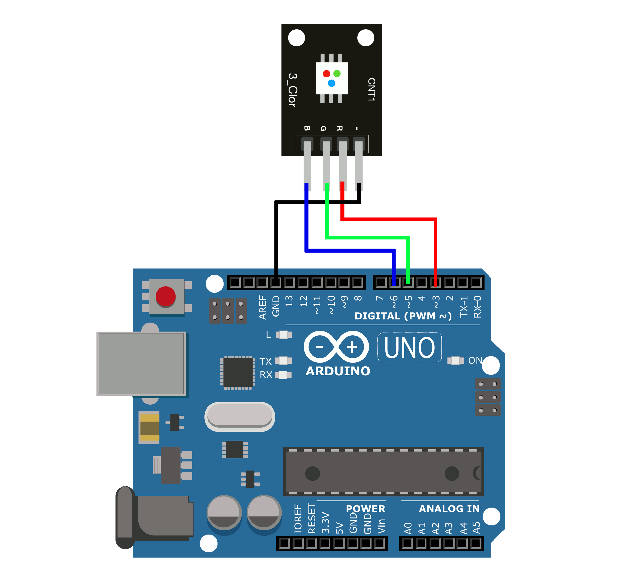
To connect RGB LED to Arduino, we need to use current-limiting resistors. This can make the wiring complex. Fortunately, we can use the RGB LED module, which already has built-in current-limiting resistors. RGB LED Module also includes four pins: Common (Cathode-) pin: needs to be connected to GND (0V) R (red): pin is used to control red

Arduino powered 300 RGB LED display. An brief "How to". YouTube
Learn how to use Arduino to control WS2812B RGB LED strip, how to control color and brightness of each individual LED on the strip, how to program Arduino step by step. The detailed instruction, code, wiring diagram, video tutorial, line-by-line code explanation are provided to help you quickly get started with Arduino.
How to setup a rgb led on arduino uno
LCDKIT can connect SPI or parallel 8-bit/16-bit display. SPI #include #define GFX_BL 23 Arduino_DataBus *bus = new Arduino_ESP32SPI ( 19 /* DC */, 5 /* CS */, 22 /* SCK */, 21 /* MOSI */, 27 ); Arduino_GFX *gfx = new Arduino_ILI9341 ( bus, 18, 1 /* rotation */ ); Parallel 8-bit low side
